
DRG
Dynaflow Announces Major Software Release
Dynaflow Research Group is pleased to announce the new major releases of all of the DRG software products, including BOSfluids, BOSpulse, ISOtracer, and BOSview. Version 7.1.
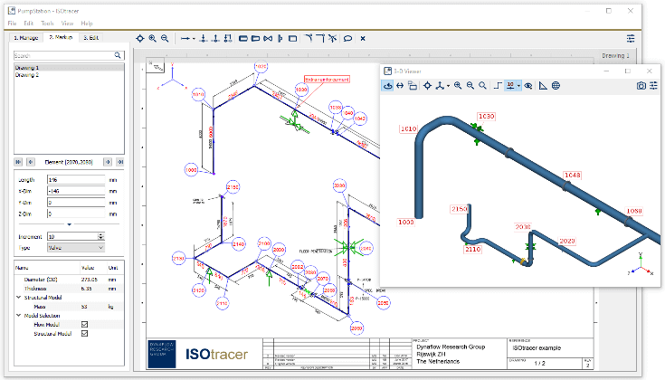
ISOtracer combines the modeling of a piping system and the marking up of isometric drawings in a single, efficient package. By tracing over a series of isometrics you can build a 3-D piping model and mark up the isometrics at the same time. This not only reduces the time required to build a model but also reduces the scope for modeling errors. Once you have build the piping model, you can export it to a multitude of analysis applications, including BOSfluids and CAESAR II.
Developed by engineers, for engineers
More than 30 years of experience with surge analyses has been incorporated into ISOtracer.
We are committed to continue doing so in every new version of the software.
While you are tracing isometric drawings, the corresponding 3-D piping model is created and displayed in real time. The 3-D model helps you navigate through your collection of isometrics in a structured manner. It also helps you verifying the correctness of your tracing operations.
Interactive Connect
Through Interactive Connect the 3-D model is connected to the markings on your isometrics. This means that ISOtracer will jump to the relevant isometric when you select a node or element in the 3-D model, and the other way around. This allows for very fast navigation and troubleshooting
ISOtracer automatically marks your isometrics with node numbers and element lengths. It also places continuation labels so that you can quickly jump to connected isometrics. Markings can be hidden or shown individually or as a group to improve the readability of the marked-up isometric.
Custom Markings can be placed on every isometric to indicate specific issues, comments, or support loads.
Since the node numbers and element lengths shown on the isometric drawings are also used in the 3-D piping model, the scope for modeling errors is significantly reduced. That is, you do not need to enter the same data twice as you would need to when you build the 3-D model after marking up the isometrics manually.
Clear Communication
Markings, including comments, are visible on the isometrics and are no longer dependent on the handwriting of the Engineer. This avoids confusion and reading difficulties.
Intelligent Routing
The built-in Intelligent-Routing capability enables you to work more efficiently. ISOtracer automatically detects changes in element direction so that you only need to specify the element lengths and not their full 3-D dimensions.
ISOtracer provides an elaborate set of features for managing and accessing all the isometric drawings associated with a piping system. For instance, with ISOtracer you can place interactive continuation labels in an isometric and directly jump to the connecting isometrics. You can also control font characteristics, hide markings individually or as a group, and export the marked up isometrics in a range of formats, including PDF, PNG and JPEG.
ISOtracer can export piping models to many commonly-used engineering applications for performing different types of analyses. For instance, it can export piping models to pipe stress applications such as CAESAR II, AutoPIPE, Rohr2 and TriFlex. It can also export models to flow and pulsation analysis applications such as BOSfluids and BOSpulse.

Dynaflow Research Group is pleased to announce the new major releases of all of the DRG software products, including BOSfluids, BOSpulse, ISOtracer, and BOSview. Version 7.1.

On July 5th Dynaflow will organize a Software User Day. During this event participants will learn about new and upcoming features, discuss existing features and meet other

Dynaflow Research Group announces the opening of a new US-based office, Dynaflow Research Group, Inc., located in Houston, Texas.
Laan van Oversteen 20
6th floor
2289 CX Rijswijk
The Netherlands
© Dynaflow Research Group BV