BOSpulse
Simulation and analysis of pressure pulsations
BOSpulse is a comprehensive software solution for performing pulsation analyses of piping systems involving reciprocating equipment. It enables engineers to model custom or predefined reciprocating equipment and the attached piping, to perform pulsation analyses, to check the results against the allowable pressure and shaking force amplitudes prescribed by the API standards, and to assess the impact of the shaking forces on the structural response of the piping system.
With BOSpulse you can:
- Determine the harmonic pressure and shaking force amplitudes in complex piping systems.
- Determine whether pressure and shaking force amplitudes remain with the API allowable limits.
- Assess API compliance for a range of operating conditions and for different scenarios.
- Model reciprocating compressors (API 618) and reciprocating pumps (API 674).
- Determine locations at which problematic acoustic and/or structural resonance occurs.
- Assess the effectiveness of mitigating measures.
- Model both the flow and structural aspects of a piping system.
- Gain detailed insight in the performance of reciprocating equipment, including the dynamic valve motion.
BOSpulse provides a complete solution for engineers looking for a tool to solve their acoustic and mechanical response problems for their reciprocating equipment.
Software capabilities
BOSpulse can calculate the flow rate, pressure and shaking force amplitudes in complex piping systems at the harmonic frequencies corresponding with the reciprocating equipment. It assumes that the flow conditions are uniform over any cross section of the piping systems, and that fluid properties are homogeneous, although they may vary in space. These assumptions are adequate for obtaining sufficiently accurate results in the typical frequency range associated with reciprocating pumps and compressors.
A collection of special flow elements enables you to build realistic 3-D models of actual piping systems. These flow elements include reducers, orifices, valves, storage tanks, dampeners, reciprocating pumps and reciprocating compressors. Fluid density variations in the system, due to temperature and/or pressure variations, are properly accounted for. BOSpulse supports pulsation analyses both for reciprocating compressors according to the API 618 standard and for reciprocating pumps according to the API 674 standard. Multiple graphical and textual tools can show if and how a piping model meets or fails the applicable API standard. BOSpulse is not limited to the flow domain; it can also perform structural modal and harmonic analyses through a structural solver interface. Because BOSpulse also provides support for modeling the structural aspects of a piping system, such as restraints and structural steel, engineers do not need to build separate flow models and structural models. This significantly reduces both the overall analysis time and the scope for mistakes. By offering both a frequency-domain and a time-domain solver, BOSpulse enables you to make a trade-off between analysis speed and accuracy. You can also use them both in a single pulsation study: use the frequency-domain solver to identify the most critical operating cases, and use the time-domain solver to obtain more accurate results for those cases.
Main reasons for using BOSpulse
- BOSpulse features a powerful and efficient user interface.
- BOSpulse performs API 618 and API 674 compliance checks.
- BOSpulse can perform coupled fluid-structure analyses.
- BOSpulse supports scenarios and parameter studies.
- BOSpulse provides an integrated steady state solver.
- BOSpulse provides time-domain and frequency-domain solvers.
- BOSpulse implements more and less detailed models for reciprocating equipment.
- BOSpulse models can be created and manipulated by custom scripts.
- BOSpulse comes with excellent support.
Features
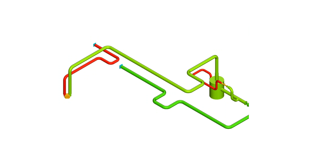
BOSpulse comes with a graphical user interface that offers a streamlined model definition procedure and extensive post-processing capabilities. The interface consists of two main areas: an area on the left that is made up of a series of tab pages providing many different input, selection and control elements; and an area on the right, named the 3-D viewer, that provides a graphical representation of the piping model. The tab pages in the left area are arranged in such a way that you normally proceed from left to right in order to define the piping model; to define the analyses that are to be performed; to run one or more simulations; and to analyze the results. The 3-D viewer provides graphical feedback of the changes you make to the piping model. It can be used to interact with the model, to select parts of the model in a graphical way, and to view the simulation results.
BOSpulse provides support for defining overlapping groups of elements and nodes that enable you to partition your model in a logical way and to apply bulk operations to different parts of the model. This can save a lot of time when you need to adapt operating conditions or pipe-related data. If your system involves multiple, (almost) identical sub-systems, you only need to model one of those sub-systems and add multiple copies of that sub-system to your model.
Parts of a model can be excluded from analyses with a few simple operations. Excluded parts are rendered translucently so that they are visible at a glance and so that you can keep interacting with them in a graphical way.
BOSpulse implements API 618 compliance checks for reciprocating compressors and API 674 compliance tests for reciprocating pumps. This means that you can very quickly assess whether your piping system and reciprocating equipment meet de applicable API allowable limits, and if not, at which locations in the system the limits are exceeded. If you are performing an analysis for a range of operating conditions, including the operating speed of the equipment, then BOSpulse will apply the API compliance checks for each operating condition, and indicate for which conditions (if any) the API allowable limits are exceeded.
API 618 compliance report example.
If the piping system involves compressors, then BOSpulse checks the pressure pulsation amplitudes within the piping and at compressor flanges; the amplitudes of the shaking forces acting on the piping and on Pressure Suppression Devices (PSDs); and the pressure drop (both the static and the total pressure drop) over PSDs.
If the piping system involves pumps, then BOSpulse checks the pressure pulsation amplitudes within the piping; the minimum pressure in the system (checked against the vapor pressure of the liquid); and the maximum pressure in the system (checked against the set pressure of safety relief valves, if present).
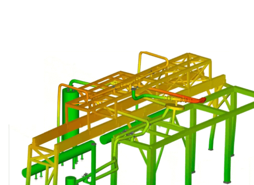
BOSpulse can not only be used to assess the shaking force amplitudes (according to the API 618 standard, Design Approach 2), but also to determine the actual impact of the shaking forces on the structural behavior of the piping system (Design Approach 3). In fact, when you use the structural solver interface provided by BOSpulse, you can run a structural harmonic analysis directly from within BOSpulse and review the computed displacements and stresses within BOSpulse too. To be precise, you can define a structural harmonic analysis that imposes the shaking forces resulting from an API 618 or API 674 analysis on a structural model of the piping system. You can specify all aspects of the structural model, including restraints, structural steel elements, and insulation layers within BOSpulse so that you do not need to set up and keep track of separate models for pressure pulsation analyses and structural analyses. BOSpulse also enables you to control the way that the finite element model is generated so that, in general, you do not need to make any manual modifications to the model before it is passed to the structural solver. This decreases the time required to perform fully coupled analyses. More importantly, it decreases the scope for errors.
The structural solver interface is currently limited to the ANSYS solver. DRG aims to extend the structural solver interface to other solvers in the future.
BOSpulse implements both the ASME B31.3 and ASME B31J piping codes. The latter is increasingly used to calculate more accurate flexibility factors, sustainable stress indices and stress intensification factors for branch connections and specific types of piping components and geometries. By adopting this piping code BOSpulse can more accurately predict the stresses and displacements resulting from harmonic pressure waves occurring in piping systems. This, in turn, helps to increase the amount of certainty which which you can determine whether the harmonic pressure waves can lead to non-acceptable structural behavior of the piping system.
You do not have to use the structural solver interface to perform a structural harmonic analysis as BOSpulse can export the shaking forces (both amplitudes and phase angles) in different formats, including spreadsheets, input files for CAESAR II and input files for Bentley AutoPIPE. In this way you can manually perform one or more structural analyses in the structural analysis tool of your choice.
If you do not use the structural solver interface, then you do not necessarily need to set up separate models for the pressure pulsation analysis and the structural analysis. BOSpulse can import piping models from different formats, including Piping Component Files, CAESAR II neutral files and spreadsheets specifying pipe profiles. BOSpulse can also export its models to CAESAR II neutral files (including structural steel files).
BOSpulse enables you to define multiple scenarios in one piping model. A scenario can be viewed as a context or scope in which the model parameters are defined. Multiple scenarios can be defined in order to study different variations of the piping model. For instance, if you are interested in the effects of an orifice diameter on the pressure pulsations amplitudes you could define multiple scenarios that specify different diameters for that orifice. In fact, you can change any model parameter, except the pipe geometry, in a scenario.
Modify groups of elements in different scenarios.
By default, a piping model comprises only one scenario, called the main scenario, that defines the primary model parameters and the piping geometry. Any other scenario is implicitly derived from the main scenario. That is, any change to the main scenario, such as a change in a pipe diameter, is propagated to all other scenarios. On the other hand, a change to any scenario other than the main scenario only affects that particular scenario.
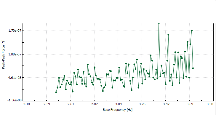
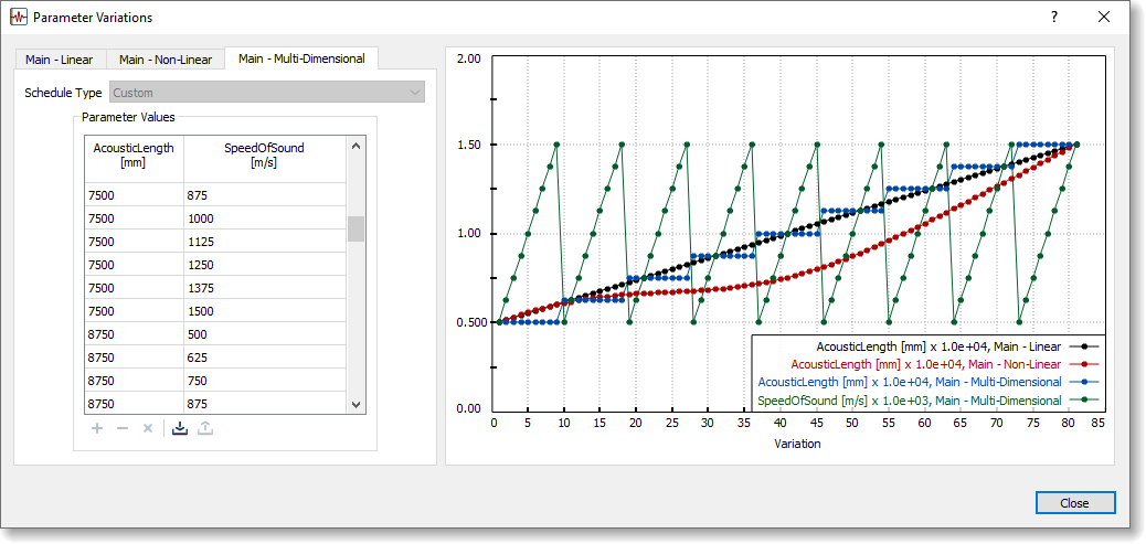
In addition to scenarios, BOSpulse enables you to specify symbolic model and analysis parameters and to perform a so-called parameter study in which the symbolic parameters are varied in a specified number of steps, called parameter variations, from a lower bound to an upper bound. For instance, instead of specifying a literal value for the API base frequency and operating speed of the reciprocating equipment, you could specify a symbolic parameter that is varied from the minimum operating speed to its maximum.
Vary the API base frequency by means of a parameter study.
This capability is not limited to the API base frequency (although that is a common application); almost any model parameter can be specified as a symbolic parameter so that you can efficiently study correlations between model parameters and the predicted pressure and shaking force amplitudes. You can also use this feature to build generic, parametric models that can be tuned to specific applications by simply adjusting the values associated with the symbolic parameters.
The number of simulations that need to be performed increases linearly with the number of scenarios and the number of parameter variations. Fortunately, BOSpulse can reduce the total analysis time by scheduling different scenarios and different parameter variations on different processor cores. BOSpulse can even take advantage of multiple processor cores when performing a single simulation with the time-domain solver.
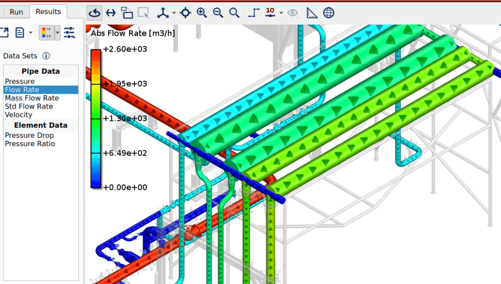
To make sense of all these simulations and their results, BOSpulse provides flexible and powerful post-processing capabilities that enables you to quickly drill down the essential information. The results can be displayed in the 3-D viewer, in a variety of 2-D graphs and in textual form. You can compare different scenarios and view how the results depend on the symbolic parameters that have been varied.
View the results from different scenarios and different parameter variations.
The steady state, or average, flow conditions are the starting point of a harmonic flow analysis, both when using a harmonic and a time-domain solver. BOSpulse therefore comes with a full-fledged steady state solver that is also used in BOSfluids, our general flow analysis package. This means that you only need to specify the relevant flow boundary conditions and BOSpulse will automatically determine realistic and consistent steady state flow conditions; there is no need to specify the flow rates manually.
The steady state solver requires the specification of at least one pressure boundary condition, typically at a boundary of the piping model. In some situations, however the exact pressure at that point is not known, but must be determined by trial and error in order to obtain a specific pressure at a compressor flange. BOSpulse can simplify and speed up this procedure by automatically tuning the steady state conditions.
BOSpulse enables you to specify a target pressure for a compressor flange node. When you do that, you also must add a so-called terminal point node to the piping model. BOSpulse will then automatically determine the required pressure at the terminal point node in such a way that the steady state pressure at the compressor flange node matches the specified target pressure. You therefore need not to know the exact pressure at the boundary of your model; you only need to indicate where you want to impose a fixed pressure boundary condition.
BOSpulse comes with both a time-domain flow solver and a frequency-domain flow solver. The former makes use of the method of characteristics to solve the non-linear, time dependent flow equations in the time domain. The harmonic pressure and shaking force amplitudes are then obtained by applying a Discrete Fourier Transform to the calculated pressures and shaking forces as function of time. The frequency-domain flow solver, on the other hand, solves a linear approximation of the flow equations directly in the frequency domain. This procedure yields the harmonic pressure and shaking force amplitudes without the need for a Discrete Fourier Transform.
Because the time-domain solver solves the non-linear flow equations, it can more accurately predict the harmonic pressure and shaking force amplitudes, especially when the flow fluctuations are relatively large in comparison with the mean flow rate. The drawback of the time-domain solver is that it can take a substantial amount of time; it is typically one or two orders of magnitude slower than the frequency-domain solver.
Because of their strengths and weaknesses, you could use the frequency-domain solver to narrow down your problem space and use the time-domain solver to perform a final assessment of the piping system under consideration.
BOSpulse provides more and less detailed models for reciprocating compressors and pumps. Both models require a description of the geometry of the cylinders, pistons, crank shaft and (connecting) piston rods, and a specification of the relevant fluid properties and thermodynamic parameters. The less-detailed models ignore the suction valve dynamics and assume that the pressure at the discharge or suction side is constant. These models essentially impose a flow boundary condition that matches the expected flow going into or coming out of the cylinders. The advantage of these models is that you do not need to know the valve characteristics and that the flow boundary condition can be generated a priori, thereby reducing the time required for a pulsation analysis.
Definition of a reciprocating compressor using the less detailed model.
The more detailed models are implemented as special flow elements that must be part of the piping model. These models no longer assumes that the suction or discharge pressure is constant; they use the pipe flow equations to determine the actual suction and discharge pressure. They also, optionally, take the valve dynamics into account. As a consequence they enable you to have a detailed look at the actual operating conditions within the cylinders and at the dynamic motion of the suction and discharge valves.
Definition of a reciprocating compressor using the more detailed model.
Whether you are using the less or more detailed reciprocating models, BOSpulse can create P-V diagrams that display the pressure in the cylinder as function of the working volume of the cylinder. If you are using the less detailed models, then BOSpulse can create the P-V diagrams without having to run an actual pulsation analysis. If you are using the more detailed models, then you must run an analysis first as the P-V data are computed during the analysis.
P-V diagram generated a priori for the less detailed model for reciprocating compressors.
BOSpulse does not limit you to the built-in models for reciprocating equipment as you can model any positive displacement equipment by specifying arbitrary periodic flow boundary conditions. That is, you can specify one period of the flow rate as a piece-wise linear function of time that BOSpulse will repeat indefinitely. The piece-wise linear function can be entered manually, specified as a mathematical expression, or imported from a text file or spreadsheet.
DRG strongly believes that the piping models you create should not be locked away in some propriety and inaccessible format. BOSpulse models and results are therefore stored in human-readable text files and HDF5 database files that can be accessed with free and open source tools. You can even access and modify these files from Python and Matlab scripts so that you can use BOSpulse as a building block in your own, custom solution procedures.
You can perfectly well manipulate BOSpulse models in a text editor.
BOSpulse model files are structured in such a way that you can easily write scripts that automatically modify and/or create these files according to your work flow. For instance, if you frequently need to analyze systems with a similar set up, you could build a base model once, then generate variations of that model with a custom script, and process those models by running BOSpulse in batch mode. You could even process the results by extracting the data of interest from the HDF5 output files.
View the contents of the HDF5 output files with free tools.
If your BOSpulse license has expired, you can still use BOSpulse to view your models and results. You can no longer, however, save any changes to your models or perform new pulsation analyses. In this way you are always able to review the models and results from past projects.
Because we frequently use BOSpulse in our engineering projects we are very able to assist you in your use of BOSpulse. Our engineers and software developers can help you setting up your piping models, including the reciprocating equipment, help you to define the analyses to be performed, and help you with the interpretation of the results. In the event that you are not able to perform a particular pulsation study yourself, you could ask us to perform the study for you.
The software developers at DRG all have a background in physics or aerospace engineering and are highly motivated to keep improving our software. This means that if you would make an investment in BOSpulse now, you are investing in a tool that continuously gets better and better. You can actually influence the development process as we actively listen to our user base; most changes and improvements in BOSpulse are the result of feedback from BOSpulse users.

Licensing, Support and Training
Release notes
Faster transient flow solver:
- The transient flow solver has been made substantially faster by applying a novel grid coarsening method. This means that the flow grid point spacing and the time step size are no longer constant throughout the entire piping mode.
- The analysis time can be reduced substantially for models involving both small pipe elements and (very) long pipe elements, and for models involving reducers.
Support for the ASME B31J piping code:
- Support for the ASME B31J piping code in addition to the ASME B31.3 piping code. The B31J piping code is increasingly used to calculate more accurate flexibility factors, sustainable stress indices and stress intensification factors for branch connections and specific types of piping components and geometries.
- For additional flexibility BOSpulse makes it possible to specify the flexibility factors and stress intensification factors manually on a branch-specific basis.
Improved structural analysis interface:
- The structural analysis interface has been extended with support for defining insulation layers; for specifying the stiffness of restraints; for specifying the finite element mesh refinement factor on an element-wise basis; and support for specifying the piping code to be used when calculating flexibility factors and stress intensification factors.
- BOSpulse is able to read the binary ANSYS results database directly; there is no longer a need to use intermediate text output files. This reduces the total analysis time significantly.
Improved reciprocating equipment models:
- The Phase Shift parameter has been renamed to Crank Angle Offset.
- Nodes of type Flange and Pulsation Suppression Devices can now refer to both reciprocating compressor boundary nodes and elements.
Automatic steady state tuning:
- Automatic steady state tuning when the pressure is known at a compressor flange node but not at the boundary of the piping system.
- Specify a Target Pressure at the flange node and change the type of the boundary node to Terminal Point. BOSpulse will then automatically determine the pressure at the terminal point node in such a way that the steady state pressure at the compressor flange node matches the specified target pressure.
Bug fixes:
- An incorrect acoustic length could be calculated for T-junctions with a specific topology.
- Only half of the shaking force would be applied to a force pair when exporting the shaking forces and when one of the nodes was not part of the structural model. BOSpulse will now apply the total shaking force to the remaining node.
Many additional features and improvements:
- Support for exporting plots containing data sets with different lengths.
- Better organization of element, node and analysis types.
- Support for specifying the acoustic length of Flange elements.
- Improved performance of the 3-D viewer.
- Support for extracting all eigenmodes within a specified frequency range when performing a modal analysis.
Version 4.0 marks a major update of BOSpulse. It brings many new features and significant improvements to existing features. Although not all changes are visible, they will help extending and improving BOSpulse in the (near) future.
Support for harmonic structural analyses:
- Support for running harmonic, structural analyses directly from BOSpulse using ANSYS as the structural solver.
- Support for reviewing the results from a structural, harmonic analysis in BOSpulse, including support for viewing the stresses, displacements and mode shapes.
- Support for parameter variations, both in the pressure pulsation analyses and in the structural analyses.
- Support for modeling the structural properties of a piping model, including restraints and structural steel.
New and more accurate time-domain solver:
- Completely rewritten time-domain flow solver that eliminates many restrictions imposed by the previous solver.
- Support for running time-domain simulations on multiple processor cores to reduce the computation time.
- More accurate flow grid generation.
New element types for reciprocating equipment:
- Two new element types for modeling reciprocating compressors and pumps.
- The reciprocating elements explicitly model the dynamic motion of the suction and discharge valves.
- Support for displaying P-V diagrams, both for the reciprocating elements and the reciprocating boundary conditions.
Support for multiple fluids in one model:
- Different fluids and/or different fluid properties can be specified for different parts of a piping model.
- Automatic adjustment of the density of gases when running a steady state simulation. An equation of state is used to relate the gas density to the pressure and temperature.
Support for reducers and mitered bends:
- Support for reducers/expanders by a model that captures the gradual change in crosssectional area and the minor loss caused by flow contraction or expansion.
- Support for mitered bends and their associated minor losses.
- Support for including minor losses at T-junctions.
Decoupled scenarios and analyses:
- Scenarios and analyses can be specified independently; one analysis type can be used with multiple scenarios and the other way around.
- Scenarios and analyses can be combined in cases for which simulations can be run. Results are associated with cases instead of scenarios.
- Multiple analyses can be edited with a single operation.
- Outdated results are no longer deleted automatically and can still be viewed after making changes to a model.
More powerful data visualization:
- The Results tab page has a new, more efficient layout.
- Graphs are embedded in the Results tab page and can be popped out when more detail is required.
- Improved support for comparing cases and data sets.
- Support for displaying element properties in the 3-D viewer.
- Support for displaying harmonic data sets in the time domain.
Components database for managing fluids and more:
- The components database enables re-use of components in different models.
- Supported components: fluid definitions, material definitions, and custom unit sets.
- Properties of (built-in) fluids can be shown graphically.
- Support for multiple database files to enable sharing of components.
New rendering engine for smoother graphics:
- The 3-D viewer is based on a new rendering engine that makes full use of contemporary graphics processors.
- Smoother graphics (no tessellation required) and better performance.
- Improved user interface responsiveness for very large models.
Bug fixes:
- The static and total pressure drop over Pressure Suppression Devices (PSDs) were not computed correctly when using the time-domain solver and the harmonic solver, respectively.
Many additional features and improvements:
- Support for selecting the Z-axis as the vertical axis.
- Support for reversing the orientation of selected elements.
- Support for cloud license keys in addition to local license keys.
- More flexible element inclusion and exclusion mechanism.
- Improved undo/redo operations.
- Many more small improvements and bug fixes.
Improved support for user-defined fluids:
- Support for specifying the physical properties of user-defined liquids and gases as function of temperature so that a more accurate wave speed can be calculated for models with significant temperature variations;
- Support for a new user-defined gas using the methodology described in the AGA Report no. 8. This allows the user to specify the composition of the natural gas.
Improved PSD handling:
- Support for automatically listing the areas and node numbers that are used in the calculation of the shaking forces acting on Pulsation Suppression Devices (PSDs);
- Support for merging elements of the type PSD in the same way as elements of the type Pipe;
- Improved support for exporting the shaking forces acting on PSDs.
Improved reciprocating equipment:
- Improved input parameters for reciprocating equipment;
- Improved calculation of the flow rate due to the new parameters Rod Diameter and Crank Clearance Volume.
Improved user interface:
- Support for undoing (and redoing) changes made to the model;
- Support for automatic adjustment of the acoustic length of pipe elements at Tjunctions;
- Support for a user-defined ambient pressures;
- Support for displaying a Bill of Quantity listing all components that make up the model;
- Support for API618 pre-study allowables;
- Addition of a static pressure drop report for API618 analyses;
- Addition of a Pipe Parameters report when using the Harmonic solver.
Support for Bentley AutoPIPE:
- Support for exporting the shaking forces to Bentley AutoPIPE.
- Support for specifying a node remap table that indicates which nodes in the BOSpulse model correspond with which nodes in the AutoPIPE model.
Harmonic solution method:
- Support for a completely new harmonic solution method that calculates the pressure pulsation amplitudes (and phase angles) directly in the frequency domain;
- Dramatic reduction in computation times, making the harmonic solution method ideal for a quick scan of a model;
- The existing transient solution method can be used to study a model in more detail as it is more accurate and provides results in the time domain too.
Support for PSD elements:
- Support for modeling Pulsation Suppression Devices (PSDs);
- Additional API compliance checks, including checks for the pressure pulsation amplitudes at compressor flanges; checks for the maximum pressure drop across PSDs; and checks for shaking forces acting on PSDs;
- Additional graphs and report options to analyze the results associated with PSDs.
New and improved file interfaces:
- Support for importing pipeline models from Piping Component Files (PCF) and from comma-separated values (CSV) files;
- Improvements to the CAESAR II neutral file interface, including support for CAESAR II version 9.
User interface improvements:
- Layout adjustments so that the user interface makes better use of the available screen estate, in particular when a model involves long scenario and/or group names;
- Support for copy/paste operations in tables;
- Support for changing the order of the scenarios;
- Support for viewing and editing the coordinates of nodes;
- Improved layout of API reports.
Support for parametric studies:
- Ability to perform sweeps over certain parameters such as the API analysis frequency or fluid wave speed;
- Use of multiple processors to reduce solver execution time;
- Coupling of the reciprocating operation speed to the API analysis frequency to simultaneously vary both model parameters.
New API compliance checks:
- Calculation of allowable shaking forces according to the API 618;
- New API result plots which show the results versus frequency including the allowable limit;
- Extended the standard API compliance reports including shaking force checks;
- New API summary reports and customizable reports which can be saved for quick regeneration after a new simulation run.
New input options:
- Support for entering element dimensions based on length and angle;
- Support for entering an ANSI nominal pipe size or schedule for pipe diameters and pipe thickness;
- Support for providing a standard density for gases to review the standard flow rate in the industry standard units.
Improved analysis options:
- Support for performing a Steady State analysis. This can be used to quickly calculate average flow rates and system pressure drops;
- Improved Results tab to review the results of all available data sets in a list and the use of sliders to go through the multiple harmonics and variations of the parameter study.
Demonstration mode:
- Demonstration mode to allow the program to run without license;
- Review old models and results after the software license has expired.
Change in the top-level tabs:
- 1. Piping to build the piping model;
- 2. Scenarios to define the models parameters for the various scenarios;
- 3. Run to run the simulation;
- 4. Results to view the computed results.
Solver improvements:
- More accurate pipe segmentation algorithm;
- Improved calculation of unbalanced loads;
- Reduced execution time of the solver;
- Support for excluding pipe elements from an API check;
- Extension of the reciprocating compressor boundary condition with support for specifying the crank and rod length;
- Extension of the Pipe element type with a minor loss coefficient.
Support for exporting to BOSview:
- Export results per scenario;
- Send a pruned results file to clients, without revealing model parameters;
- Clients can download the free standalone application BOSview;
- Clients can see the piping model and results in a similar way as users do in the Results tab.
Support for saving 2-D plots:
- Save the setup of a 2-D plot to a model file;
- Recreate all saved plots after running a new simulation;
- Export all saved plots to multiple image or data files.
Improved input and output:
- Handle CAESAR II version 7 neutral files;
- Show a warning when saving a model in a new version;
- Better handling of errors while reading a results database.
Improved user interface:
- Improved layout of the Scenarios tab;
- Support for duplicating groups of elements;
- Use the global F5 shortcut key to run a simulation;
- Improve the handling of elements of type None;
- Improved warning and error messages when running a simulation;
- Change of some English units to better adhere to industry standards;
- Support for measuring the distance between nodes with the Ruler tool.
The initial version of BOSpulse is a spin-off from BOSfluids 4.6, a proven fluid flow solver which has been on the market since 1995. The main features of BOSpulse 1.0 are:
Intuitive user interface:
- intuitive guidance through the analysis process using numbered tabs;
- clear highlighting of options that require input;
- continuous check for correct input values.
3-D Interface:
- interactive visualization of the model while it is built;
- clear and intuitive node numbers, labels, rotating, color settings, element visualization, etc.;
- editing options to select, alter or insert (groups of) elements from the viewer.
Groups and labels:
- creation of standard and custom element and node groups;
- simultaneous editing of elements at the group level;
- labeling of elements and nodes for easy reference during post-processing.
Scenario Builder:
- support for creating multiple variations on a model;
- bundling of all scenarios into one input file and one results data base.
Import/Export features:
- import CAESAR II models in BOSpulse;
- export BOSpulse models to CAESAR II;
- export BOSpulse harmonic force results to CAESAR II;
- import BOSfluids models.
Post-processing:
- 3-D viewer clearly shows all pipe sections where the resulting pressure pulsation is over the allowable;
- 2-D graph manager to plot (several) results in one graph;
- smart database structure for storing all output in one file;
- reports providing a detailed overview of the complete API check.
Documentation available on the website:
- elaborate tutorials including theoretical background;
- video demonstrations.
BOSpulse videos
BOSpulse 4.0 release
We proudly present the newest release of BOSpulse (4.0).