Surge Analysis Made Easy
BOSfluids enables you to perform surge analyses in an interactive and visual way, giving you lots of opportunities for exploring your problem space fast and efficiently.
BOSfluids is more than a surge analysis tool as it can simulate general steady-state and transient flow conditions in piping systems, and help you perform coupled fluid-structure analyses.
Developed by engineers, for engineers
Key Capabilities
More than 30 years of experience with surge analyses has been incorporated into BOSfluids.
We are committed to continue doing so in every new version of the software.
- 3D Piping Models
- High Performance
- Advanced Modelling
- Data Integration
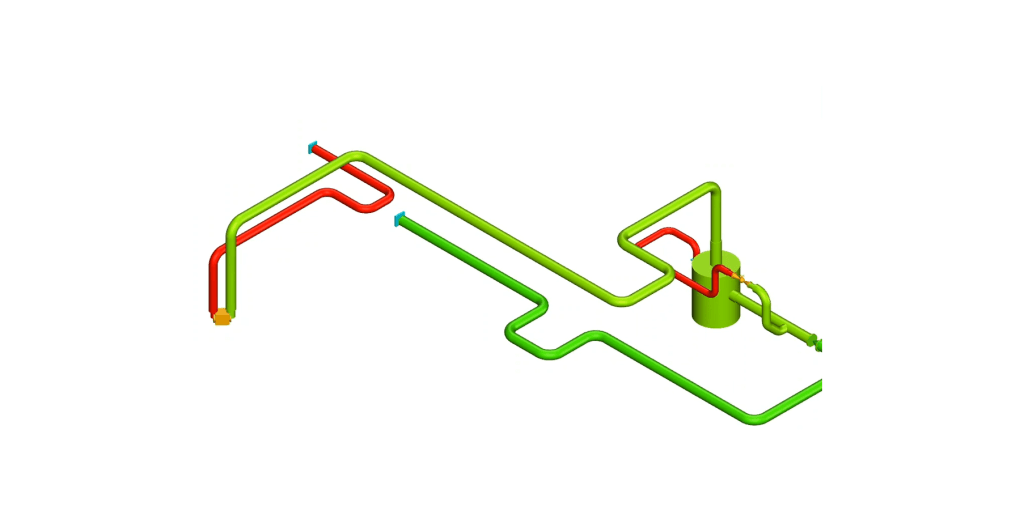
Because BOSfluids works with 3-D piping models you can directly correlate your model with the actual piping system, helping you avoid making mistakes. What is more, 3-D models result in accurate predictions of the magnitude, direction and exact location of the unbalanced fluid forces. This makes BOSfluids an ideal tool for combined fluid-structure analyses.
BOSfluids is one of the most efficient surge analysis applications available on the market. It is at least 10-100x times faster than most other applications which gives you great benefits: significant time savings, analyses of much larger models, and the simulation of many scenarios at once.
BOSfluids comes with advanced surge analysis technology that enables you to perform accurate transient analyses, combined fluid-structure analyses, two-phase flood and drain analyses, control system simulations, tube rupture analyses, pump failure simulations, automatic orifice sizing, and much more. BOSfluids can handle systems filled with liquids and gases, and comes with a flexible components database.
BOSfluids is designed to interact with other software packages. It can import and export piping models in common formats, including PCF and EPANET. It can also export unbalanced forces to various structural analysis programs, including CAESAR II, ANSYS and AutoPIPE. When exporting to CAESAR II, BOSfluids can set up everything that is needed to perform a dynamic structural analysis.
Available Solvers And Analyses
- Quasi Steady State Solver
- Transient Flow Solver
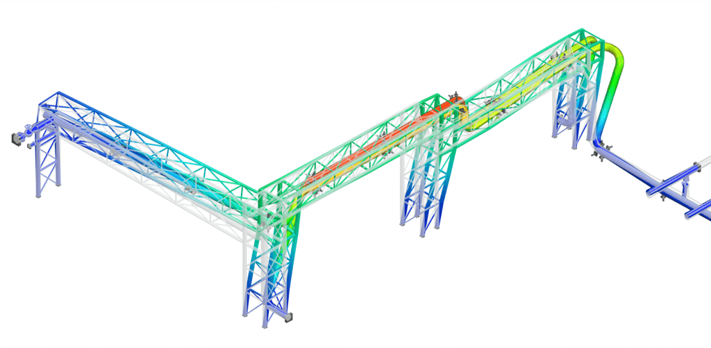
- Coupled Fluid-Structure Analysis
- Steady State Impact Analysis
The steady state solver enables you to assess the impact of system changes on the steady state process conditions. It can be used to determine the optimum size of orifice plates, pumps and other equipment. It can also be used for line sizing and layout optimization, and other types of parameter studies.
BOSfluids Applications
- Water Hammer Analysis
- Line Sizing For Process Industry
- Pump Failure Simulations
- Multiple Scenarios In One Model
- Flow Control Systems
- Two-Phase Flood & Drain Analyses
- Tube Rupture Simulations
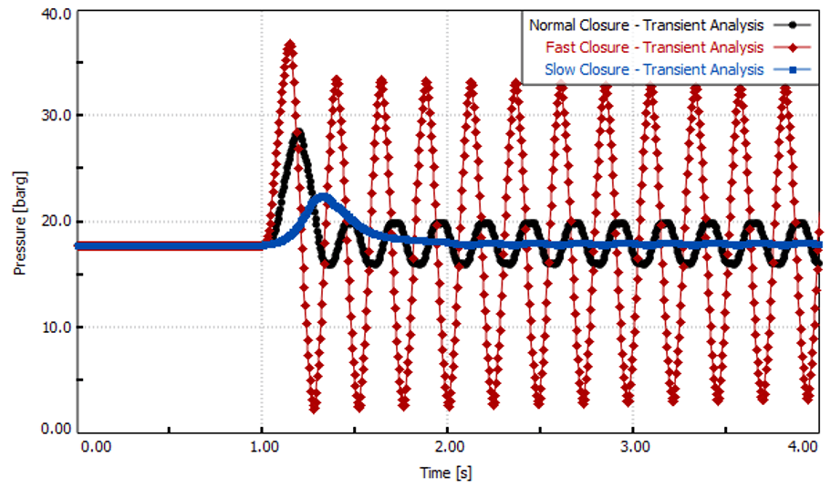
Water Hammer Analysis
In case of an emergency, one or more ESD (Emergency Shutdown) valves may need to close immediately. The rapid closure of these valves can cause significant fluid-induced forces on the attached piping system, a phenomenon known as water hammer.
With BOSfluids, you can analyze the maximum surge pressure, find the dynamic forces working on the piping system, and use these forces to perform a structural analysis using the structural interface with a third-party structural stress solver.
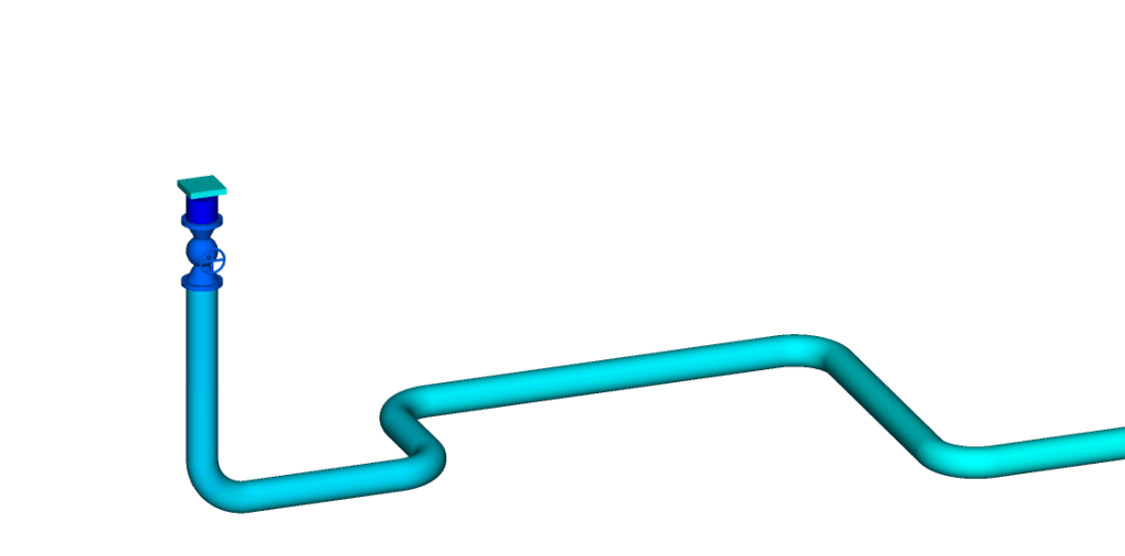
Line Sizing For Process Industry
Line sizing is an important first step for any piping system. BOSfluids offers an excellent steady-state flow solver with the optimization features a process engineer needs.
Since BOSfluids includes both a 2-D network viewer and a 3-D piping viewer, any BOSfluids model file is ready to perform a pressure surge analysis and even pipe stress analysis in later engineering stages.
Ask us for more information on the BOSfluids Steady State license for an economical engineering solution.

Pump Failure Simulations
Pump failure events, involving a sudden loss of power to one or more pumps, can lead to pressure surges and flow conditions exceeding the design specifications of a piping system.
A detailed pump failure model is available in BOSfluids that predicts how a pump spins down after its power has been cut.

Multiple Scenarios In One Model
A scenario can be viewed as a context or scope in which the model parameters are defined. Multiple scenarios can be defined to study different variations of the piping model.
For instance, if you are interested in the effects of the valve closure time on the maximum surge pressure peak, you would only need to change this single parameter in the scenarios and you can compare the impact of this in the output processor.
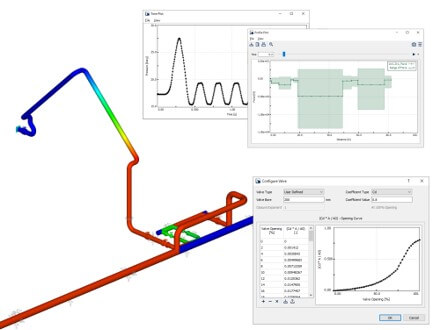
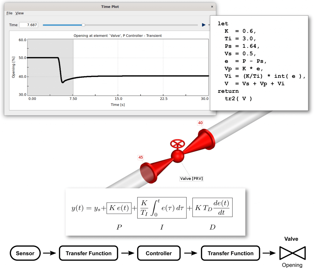
Flow Control Systems
BOSfluids provides extensive support for simulating automatic control systems that adjust flow elements in response to changes in the flow conditions or to external events, such as timer switches.
This means that you can use BOSfluids to set up, tune and assess control systems in a virtual way so that you can save time and costs, and reduce the risk of affecting a operational system in a negative, or even damaging way.
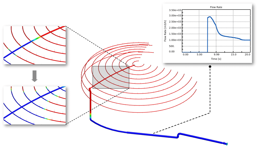
Two-Phase Flood & Drain Analyses
When an empty firewater system is filled during a fire situation, it can be subjected to significant loads resulting from the liquid interface moving through the system. Indeed, there have been multiple incidents involving firewater systems in which these forces caused significant damage to the piping system.
The two-phase Flood & Drain model implemented in BOSfluids can be used to simulate the rapid filling of empty, or gas-filled, piping systems. This makes BOSfluids a unique and effective tool for predicting and mitigating the forces that are exerted by the liquid on the piping system.
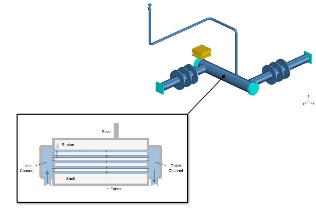
Tube Rupture Simulations
Tube rupture in a tube-and-shell heat exchanger can lead to overpressure situations in the shell or the tubes. The tube rupture model implemented by BOSfluids can be used to simulate the discharge of a high-pressure gas or liquid from one or more ruptured tubes into a low-pressure shell.
The model supports phase transitions due to flashing and also accounts for pressure losses within the tubes and pressure changes due to temperature changes.
Latest News & Insights

Dynaflow Announces Major Software Release
Dynaflow Research Group is pleased to announce the new major releases of all of the DRG software products, including BOSfluids, BOSpulse, ISOtracer, and BOSview. Version 7.1.

DRG presents at OpenFoam Workshop 2023
Dynaflow Research Group has given a presentation today “Validating and extending the use of BOSfluids using OpenFOAM” at the OpenFOAM Event at the TU Delft organized by the Dutch OpenFOAM user group.

Annual User day
On July 5th Dynaflow will organize a Software User Day. During this event participants will learn about new and upcoming features, discuss existing features and meet other
Boost Your Knowledge
Learn all about the effects of pressure surges on piping systems and how to perform a Surge Analysis using BOSfluids.